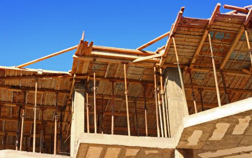

The arrangement of a building or structure shows the foundation plan at ground level in line with its blueprints, enabling accurate excavation where necessary and exact designation of the building’s position and orientation. The foundation plan drawings and requirements provided by the architect or engineer are followed in its layout.To understand layout, or the laying out of a building, one needs understand the technical terms listed below, which are associated with this activity.
BASELINE
A line that is drawn straight across a building to show which corners are on the ground is called a baseline. It might be a curb, the boundary of the region, the outer edge of a road, or just a line that joins any two locations.
Horizontal Regulators
Horizontal controls are those points that are known to have coordinates with respect to another location. These points are then used in a number of ways to locate other places, such as a plan’s corners. There should be a large number of control points to guarantee that each foundation plan point is positioned appropriately on the ground.
VERTICAL CONTROLS
In order to place design points on the works at the proper levels, vertical control points of known height with respect to a specified vertical datum are produced. In actual use, vertical controls consist of 100 mm long, 20 mm diameter steel bolts with known decreasing levels hammered into the ground under ledges, walkways, steps, etc.
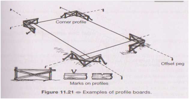
BATTERBOARDS AND OFFSET PEGS
In the places indicated by the points on the pattern, pegs are driven into the earth. When excavation for the foundation begins, the corner pegs will be gone. To stop them, offset pegs are used in lieu of these extra pegs. Batter boards are often positioned next to each offset peg and used to relocate the points after the excavation is finished.
AWAY FROM AN USUAL BUILDING SITE
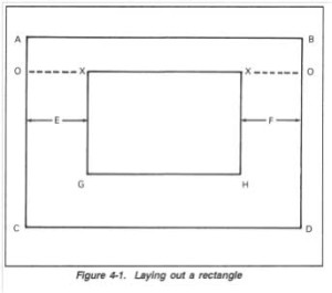
Assess the building area’s maximum external bounds (AB, CD, AC, and BD), beginning at a baseline (line AB in Figure 4-1) that is parallel to the structure.
Finding point X may be done by computing its x distance along line AB and its y distance along lines AC and BD, respectively, assuming we know its coordinates (x,y) in reference to point A. These two locations may be joined to produce line XX. Points G and H are located by drawing a straight line using the 3-4-5 triangle approach. Next, the line shows the known distances XG and XH. Once they have been determined, drive stakes into each of the four corners (X, X, G, and H). Every step establishes precise dimensions.
DISCRETE BUILDING SITE SETTING UP
In situations when the building’s contour is not a rectangle, the procedure for identifying each point is the same as that which is explained for drawing out a simple rectangle. However, there are still more points to be made, and there’s a greater chance that a little error will be found when the work is finally proofread. It is reasonable to begin by putting out a sizable rectangle that completely or mostly encloses an asymmetrical construction. As seen in Figure 4-2, this is HOPQ. After this is decided, the remaining portion of the pattern will consist of small rectangles that may be individually adjusted and shown. These rectangles are shown as LMNP ABCQ, DEFG, and IJKO in Figure.
ADVANCED LINES
Given that the building’s corner pegs will be removed during excavation, these locations are relocated beyond that boundary by extending lines and driving pegs into the ground. The steps listed below relate to Figure 4-4 on page 4-4 as the basic configuration; they must be altered to accommodate alternative or
more difficult layout issues:
Step 1: Set up batter boards following the location and dipping of stakes A and B
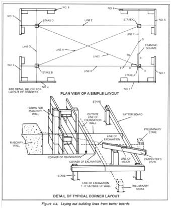
Draw a line in chalk (X) connecting batter board 1 to batter boards 2, 3, and 4.
Stakes A and B are under board 3.
Step 2: Locate and dip stake C, then build batter boards 5 and 6.
After crossing stakes A and C, extend Chalk Line Y from Batter Board 2 to B act Board 6.
Step 3: Set up the batter boards 7 and D after finding and dipping the stake.
Chalk line Z should be extended across stakes C and D from batter board 5 to batter board 7.
Move line O over stakes D and B and extend it from batter board 8 to batter board 4.
It is necessary for the excavation to exceed the planned size in cases when the foundation walls are broad at the base and go beyond the building’s external measurements. Measure out the necessary distance from each batter board’s construction line, then extend lines between these places outside of the initial layout to get the proportions of this excavation.